Bolt-on Electrical Stimulation Drive
Low-Cost Add-On for Converting a Microscope into a Fully Automated Electrical Stimulation Screening Platform
About
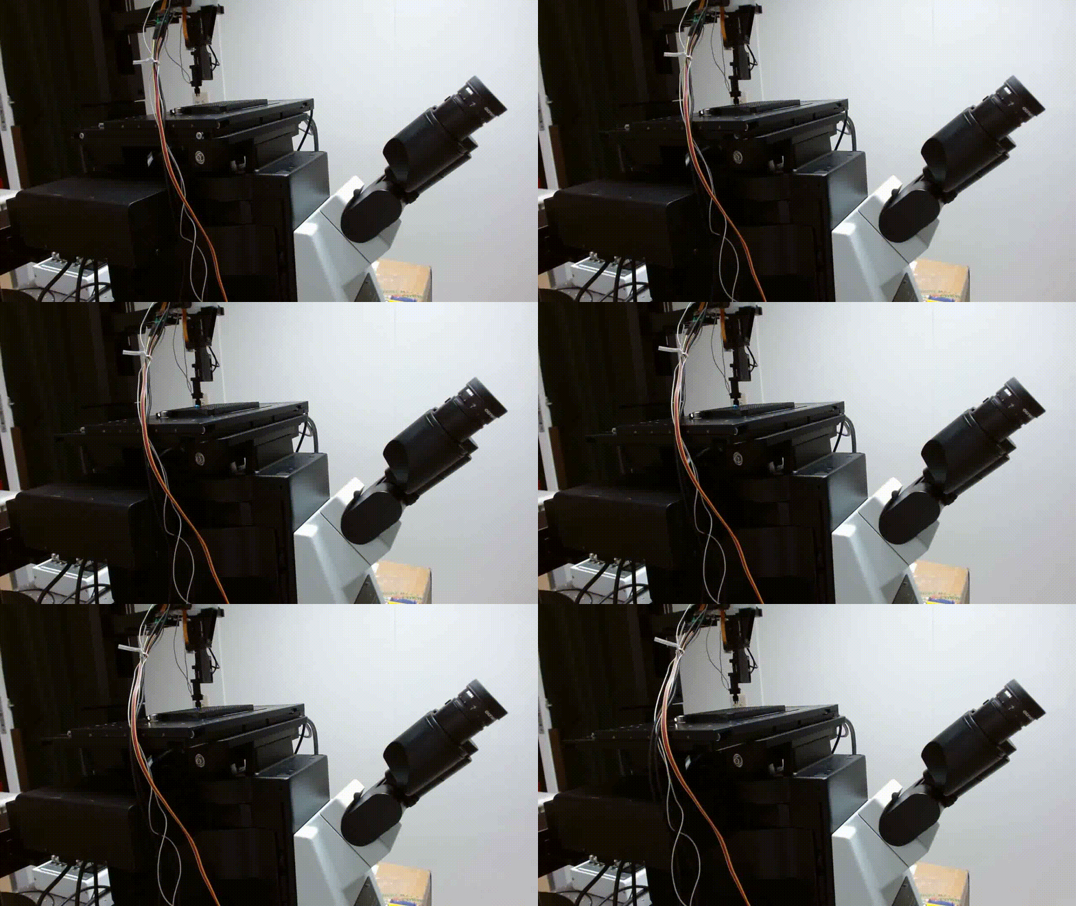
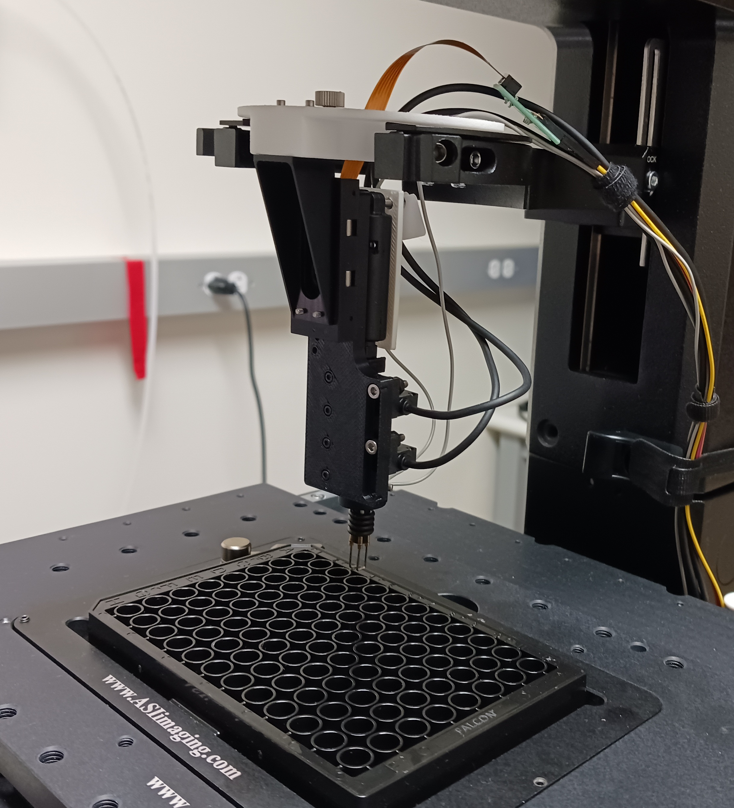
This open-source “bolt-on” electrical stimulation device is designed to electrically excite cells in multiwell plates, allowing a standard motorized inverted microscope to be upgraded to a fully automated electrical stimulation screening platform. The design is based on previous work by the GENIE Project Team at HHMI Janelia Research Campus, where it was used to screen hundreds of variants of genetically encoded fluorescent protein sensors such as jGCaMP8, Voltron2 and iGABASnFR2.
The stimulation hardware comprises an electrode drive and an interface board. The electrode drive lowers platinum electrodes into the wells of a 96-well plate. The interface board contains the electronics to power the electrode drive and can be controlled manually using buttons or via external TTL signals.
The cost to manufacture the drive itself is less than \$500. The platinum electrodes used here (1 mm diameter) are the most expensive part of the design (>\$1,000).
Features
- Quick mounting on the condenser holder on virtually any inverted microscope
- Adjustable height and travel range of drive to accommodate different screening plates
- Manual (push-button) or digital control of electrode movement
- Digital confirmation of electrode position
Electrode drive
Materials
Off-the-shelf
| Quantity | Item | Description | Link | Additional notes |
|---|---|---|---|---|
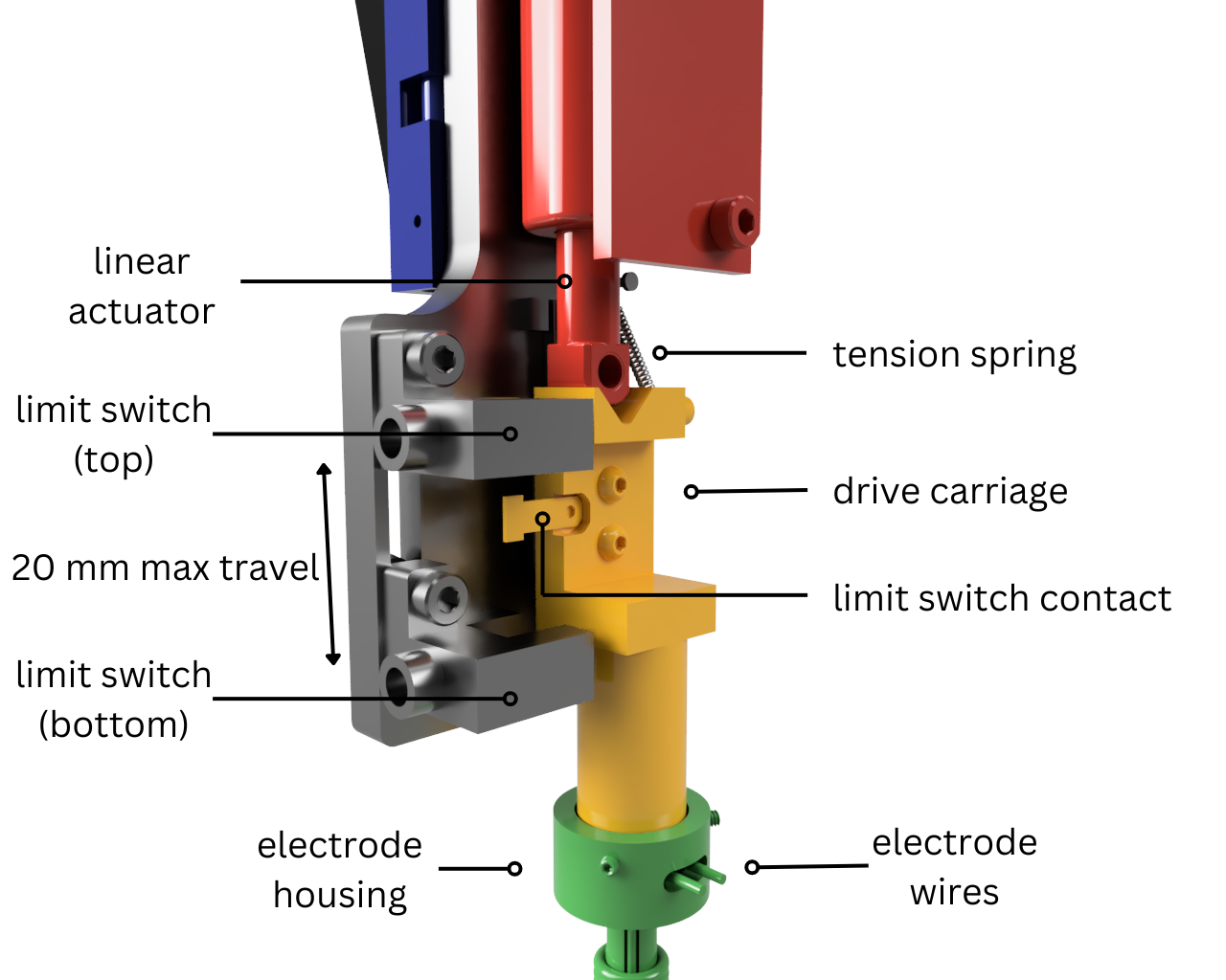
| 1 | Linear actuator | Actuator for moving the electrode into the well | PQ12-100-6-S (Digikey) | |
| 2 | Limit switch | Sets upper and lower travel limits of the linear actuator | PM-F25 (Digikey) | The limit switches are mounted in a groove on the actuator mounting bracket. Their relative position can be adjusted to modify the travel range of the electrode |
| 1 | Carriage rail | Holds the electrode carriage | 8381K39 (McMaster) | |
| 1 | Tension spring | Spring for keeping tension on the carriage, returning it back to upper travel limit | 5108N002 (McMaster) | One end of the spring is wound around a |
| 1 | Limit switch contact | Tag on the electrode carriage that activates the limit switches | 1267 (Digikey) | The small tag opposite of the hole was cut off |
| 2 | Electrode wire (Platinum) | Platinum rod; diameter 1 mm, length 300 mm | PT-M-02-R (American Elements) | Contact American Elements to get a quote |
| 3 | O-ring | For securing the electrodes to the outside of the housing | 9262K252 (McMaster) | |
| 1 | Condenser mounting bracket | Connects to condenser mount to hold the rest of the assembly | MS-KIT-Z-1 (Newport) | |
| 1 | Vertical adjuster | Linear stage for setting the vertical position of the electrode (13 mm travel range) | MS-500-X (Newport) | |
| 1 | Vertical adjustment screw | Adjustment screw for the vertical adjuster | Adjustment Screw, Tiny Knob, 28.7 mm Travel, Ball Tip, 6-80 (Newport) | The vertical adjuster comes with an adjustment screw which can be used, but it is too short to be used conveniently; therefore, this is a replacement for that screw |
| 1 | Spring mount post | Post on the actuator mounting bracket that holds one end of the tension spring | H9004-01 (Digikey) | Press fit into the actuator mounting bracket |
| 2 | 18-8 Stainless Steel Socket Head Screw, Thread Size: 2-56, Length: 3/16” | Connect mounting bracket to vertical adjuster | 92196A076 (McMaster) | |
| 2 | 18-8 Stainless Steel Socket Head Screw, Thread Size: M4 x 0.7 mm, Length: 10 mm | Connect retention bracket to mounting bracket | 91292A019 (McMaster) | |
| 4 | 18-8 Stainless Steel Socket Head Screw, Thread Size: 0-80, Length: 3/8” | Connect vertical adjuster to condenser mounting bracket | 92196A057 (McMaster) | |
| 2 | Button Head Hex Drive Screw, Thread Size: 10-32, Length: 1/2” | Connect electrode carriage to carriage rail | 92095A452 (McMaster) | |
| 5 | Alloy Steel Socket Head Screw, Thread Size: 6-32, Length: 3/8” | For mounting the carriage rail on the actuator mounting bracket; mounting the tension spring on the carriage | 91290A022 (McMaster) | |
| 3 | 18-8 Stainless Steel Cup-Point Set Screw, Thread Size: 1/4”-20, Length: 1/4” | For connecting electrode housing cap to electrode carriage | 92015A205 (McMaster) | |
| 3 | 18-8 Stainless Steel Socket Head Screw, Thread Size: 4-40, Length: 1/2” | For connecting the condenser mount to the condenser mounting bracket | 92196A049 (McMaster) | |
| 2 | 18-8 Stainless Steel Socket Head Screw, Thread Size: M2.5 x 0.45 mm, Length: 8 mm | For mounting the limit switches on the actuator mounting bracket | 91292A016 (McMaster) | |
| 2 | Black-Oxide Steel Hex Nut, Thread Size: M2.5 | For mounting the limit switches on the actuator mounting bracket | 90593A025 (McMaster) |
3D printed
| Quantity | Item | Description | Link |
|---|---|---|---|
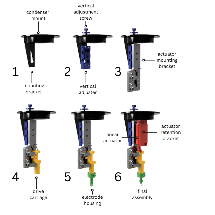
| 1 | Condenser mount | Slides into the condenser slot on the microscope. Note: this piece will need to be custom-made for different microscopes. It was tested with an Olympus IX-83. | STL |
| 1 | Actuator mounting bracket | Holds the actuator, rail, and limit switches | STL |
| 1 | Electrode carriage | Carriage that slides on the rail and holds the housing | STL |
| 1 | Electrode housing | Holds the electrode wires | STL |
| 1 | Actuator retention bracket | Holds the actuator | STL |
Assembly
The entire drive design is available for download as a STEP file to simplify assembly.
Interface board
The interface board is a PCB that controls the linear actuator and receives signals from buttons, external control logic, and limit switches.
Electrical design
The general principle of operation of the circuit is as follows: when neither the top or bottom limit switches are activated, the linear actuator (M1 on the schematic) receives inputs from the two relays UP_RLY1 and DWN_RLY1. These relays send +5V or 0V on either the + or - side of the actuator, enabling it to change direction. When either limit switch is tripped, indicating that the actuator is at the top or bottom of its’ travel range, the transistor Q1 switches off. The limit switches are only active when the actuator is moved in the corresponding direction, e.g. UP_LIM1 only gets powered (+5V on +V) when the command to move up is given (either with the manual switch SW_UPDWN1 or the BNC input DAQ_IN_UP1). When either limit switch is tripped or the movement command is stopped, the transistors Q1 and Q2 driving the relays turn off and the corresponding actuator input line goes to 0V.
Printed Circuit Board (PCB)
The 2-layer PCB for the schematic shown above can be downloaded as a Gerber zip file or as a KiCAD PCB file. I used OSHPARK to manufacture the PCB. For a 2-layer 4.00 x 3.00 inch (101.6 x 76.2mm) board, it will cost ~$60. Other PCB manufacturers can also be used.
The full bill of materials (BOM) is here as an Excel file.
PCB enclosure
The PCB enclosure can be 3D printed as two separate pieces (enclosure body and lid). The front of the enclosure has BNC inputs and outputs for driving the actuator and sensing the position. The lid has spaces for two rocker switches.
| Quantity | Item | Description | Link | Additional notes |
|---|---|---|---|---|
| 1 | Enclosure body | Main body of the PCB enclosure | STL | Should be printed the way it is shown in the image (standing upright). Ensure that supports are enabled to properly reproduce the connector cutouts |
| 1 | Enclosure lid | Lid for PCB enclosure | STL | Should be printed the way it is shown in the image (labels facing up) to ensure that the labels are properly printed |
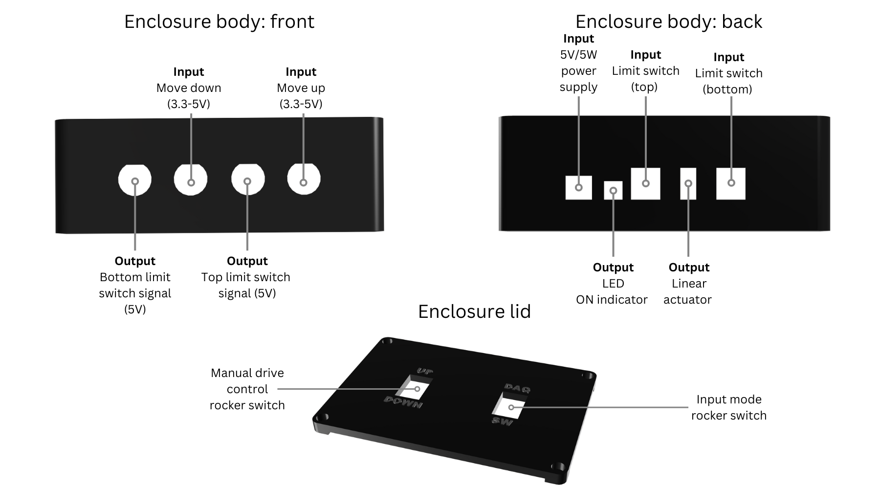
Enclosure body: front
| Input/Output | Description | Additional notes |
|---|---|---|
| Output | Bottom limit switch signal BNC (5V) Active LOW; this line goes LOW when the bottom limit switch is activated. This line can be monitored using a DAQ or microcontroller to confirm that the drive has reached the bottom position. | |
| Input | Move down command signal BNC (3.3-5V) | To move actuator down, set this line HIGH and the “Move up” line low |
| Output | Top limit switch signal BNC (5V) | Active LOW; this line goes LOW when the top limit switch is activated. This line can be monitored using a DAQ or microcontroller to confirm that the drive has fully retracted from the well. |
| Input | Move up command signal BNC (3.3-5V) | To move actuator up, set this line HIGH and the “Move down” line low |
Enclosure body: back
| Input/Output | Description | Additional notes |
|---|---|---|
| Input | Barrel jack (power input) | |
| Output | LED ON indicator | |
| Input | Top limit switch connector | Wiring: pin 1 (left): +V (brown); 2: 0V (blue); 3: Out2 (white, but does not need to be connected); 4: Out1 (black). See datasheet for details |
| Output | Linear actuator power | The pins should connect to pins 2 (black) and 3 (red) on the extension cable that goes to the PQ12 actuator. The other pins in the cable can remain unconnected. Note: the polarity may need to be flipped to make sure the actuator goes up and down when the corresponding buttons are pushed. See datasheet for details. |
| Input | Bottom actuator connector | Wiring: pin 1 (left): +V (brown); 2: 0V (blue); 3: Out2 (white, but does not need to be connected); 4: Out1 (black). See datasheet for details |
Enclosure Lid
| Description | Link |
|---|---|
| Input mode rocker switch (DAQ/SW) | GRS-4022-0001, Mouser |
| Manual drive control rocker switch (UP/DOWN) | GRS-4023C-1300, Mouser |
Input Mode Rocker Switch (DAQ/SW) Wiring Information
| Pin on the switch | Pin on SW_DAQ_OR_MAN_1 |
|---|---|
| Pin 1 (common1) | 2 |
| Pin 2 (common2) | 5 |
| Pin 1a | 3 |
| Pin 1b | 1 |
| Pin 2a | 6 |
| Pin 2b | 4 |
Manual Drive Control Rocker Switch (UP/DOWN) Wiring Information
| Pin | Pin on SW_UPDWN1 |
|---|---|
| Pin 1 (common) | 2 |
| Pin 1a | 1 |
| Pin 1b | 3 |
Ensure proper orientation of the switch in the lid cutout for label consistency.
Additional hardware/software requirements
- To automatically trigger the drive, use two digital output pins on an Arduino or an NI DAQ. Two more digital inputs can be used to confirm the electrode position.
- The electrodes need to be connected to an electrical stimulator such as a A385 (WPI) or Model 4100 (A-M systems).
- Data acquisition software such as ACQ4 (Python-based, free), Wavesurfer (MATLAB-based), or NI LabVIEW can be used to synchronize camera frames with the stimulation.
Known issues, planned improvements
- Cannot use condenser (i.e. transmitted-light imaging such as phase contrast) during operation
